


I. Introduction
YX3000 Series Frequency Inverter provides users with an RS485 protocol communication interface commonly used in industrial control. MODBUS standard communication protocol is adopted. Support RUT and ASCII these two transmission methods. The detailed MODBUS protocol and the parameter definition of the inverter communication protocol are introduced in the inverter user manual.
II. Requirements for Communication Cases
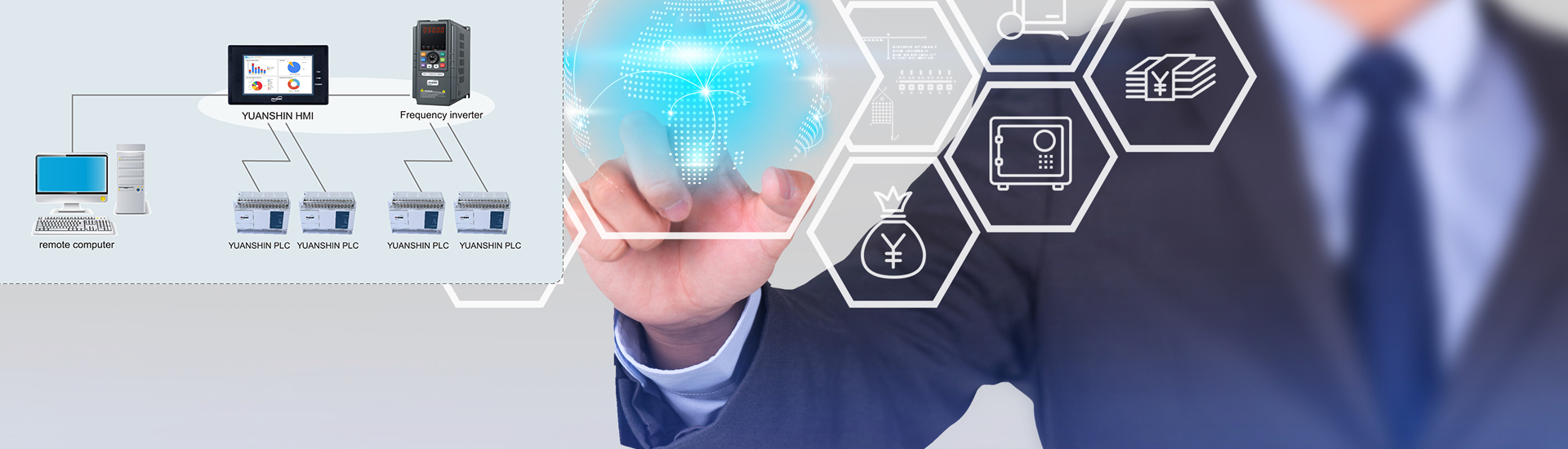
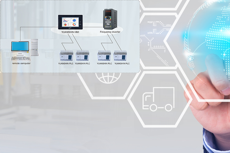
YX3000 Frequency Inverter and Samkoon SK043A touch screen communicate through MODBUS, which realizes the functions of controlling the start and stop of the inverter, frequency setting and inverter status monitoring through the touch screen.
III. Communication Parameters
In order to realize the normal communication between the inverter and the touch screen, the communication parameters of the inverter are consistent with the touch screen, and the correct communication port should be selected. The Modbus RTU transmission mode is used in YX3000, the communication format is the 1-8-1 format, i.e., data byte (eight binary) transmission, comprising 1 start bit, 8 data bits, 1 odd / even parity, 1 stop bit and CRC (Cyclic Redundancy Check).
IV. Parameter Setting
|
Function code |
Name |
Predetermined range |
Smallest unit |
Factory setting |
Set value |
|
P0.01 |
Frequency setting channel selection |
0: Panel analog potentiometer; 1: Keyboard ▲, ▼ key setting; 2: Digital setting 1, operation panel; 3: Digital setting 2, terminal UP/DOWN adjustment; 4: Digital setting 3 , serial port setting; 5: VI analog setting (VI-GND); 6: CI analog setting (CI-GND); 7: Terminal pulse (PULSE) setting; 8: Combination setting (see P3.00 parameter); |
1 |
0 |
4 |
|
P0.03 |
Run command channel selection |
0: Run frequency channel of the operation panel 1: Run command channel of the terminal 2: Run command channel of the serial port |
1 |
0 |
2 |
|
P3.09 |
Communication configuration |
LED Bit0: baud rate selection 0 : 1200BPS 1 : 2400BPS 2 : 4800BPS 3 : 9600BPS 4 : 19200BPS 5 : 38400BPS LED Bit1: data format 0 : 1 - 7 - 2 format, no check 1 : 1 - 7 - 1 format, odd parity 2 : 1 - 7 - 1 format, even parity 3 : 1 - 8 - 2 format, no check 4 : 1 - 8 - 1 format, odd parity 5 : 1 - 8 - 1 format, even parity 6 : 1 - 8 - 1 format, no check LED Bit2: Communication mode 0 : MODBUS , AS C II mode 1 : MODBUS , RTU mode |
1 |
063 |
163 |
|
P3.10 |
Local address |
0 ~248 0 : broadcast address 248 : frequency converter as host address |
1 |
1 |
1 |
Note: Other functions of the inverter can be set by referring to the use manual for inverters.
V. Communication between the Inverter and the Touch Screen
Below we detail the general process of establishing communication between YX3000 Frequency Inverter and Samkoon SK-043 touch screen.
RS485 communication is adopted in YX3000 Frequency Inverter and SK43 touch screen, and SKWorkshop configuration editing software designed for Samkoon SK is used in the touch screen programming software .
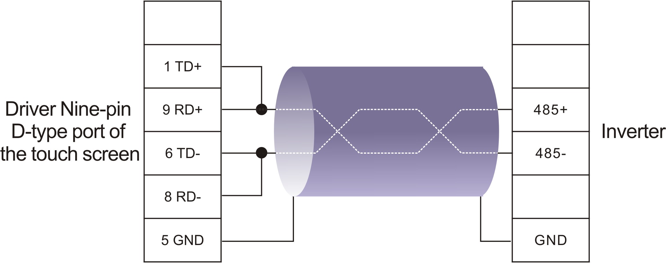
Connection
The back of the touch screen is a communication port for an external 24VDC power terminal and a nine-pin D-type male socket. The serial communication pins are defined as follows:
|
Pin number |
Definition |
|
1 |
TD+ |
|
2 |
RXD |
|
3 |
TXD |
|
4 |
NC |
|
5 |
GND |
|
6 |
TD- |
|
7 |
RTS |
|
8 |
RD- |
|
9 |
RD+ |
The RS485 communication method is adopted between the inverter and the touch screen, and the cable connection diagram is shown in the figure below.
VI. Cases of the touch screen project
- Enter THE SKWorkshop interface;
- Open the file;
- New project;
- Enter the name of the project to be created in Project Name.
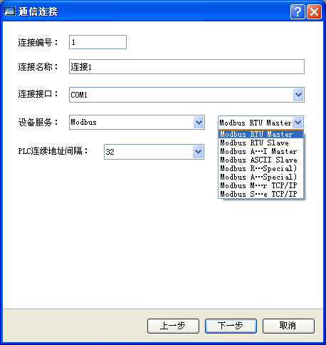
- Modbus RTU Master: a touch screen to be as the Modbus master station, the device as the slave station (i.e., conventional Modbus);
- Modbus RTU Slave: a touch screen to be as the Modbus slave station, the device as the Modbus master device;
- Modbus ASCII Master: a touch screen to be as the Modbus master station, the device as the slave station (ASCI communication) ;
- Modbus ASCI Slave: a touch screen to be as the Modbus slave station, the device as the master station (ASC communication) ;
- Modbus RTU Special: a touch screen to be as the Modbus master station , the device as the slave station (write data function code is 0x10, regardless of the length of the write data) ;
- Modbus Special ASCI: a touch screen to be as the Modbus master station, the device as the slave station (write data function code is 0x10, regardless of the length of the write data, the ASCI communication) ;
- Modbus Master TCP / P: a touch screen to be as the Modbus master station , the device as the slave station (TCP / IP communication) ;
- Modbus Slave TCP / P: a touch screen to be as the Modbus slave station, the device as the master station (TCP / P communication).
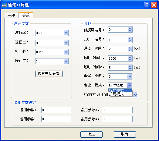
PLC continuous address interval: the number of continuous addresses that can be read at a time (Note that when communicating with a single-chip device or inverter device, if the register address of the device is not continuous or the address of the register is not an integer multiple of 32, for example the address of the developed single-chip when there are only 20, this can be changed to 1).
Connection parameter setting