


I. Overview
A metal wire tool electrode (also called an electrode wire) is used by the wire cutting machine to process a workpiece along a given geometric pattern track, under the principle of pulse electric discharge to corrode metal. The fast-moving wire cutting machine emerged in China in the 1970s and has been gradually widely used in the processing of metal parts such as molds with high accuracy requirements and complex shapes.
II. Comparison before and after applying YX3500
The electrical and control system of the wire cutting machine is generally divided into: a microcomputer control part, a high-frequency power supply part and a wire drum motor control part. The wire drum motor control part controls the motor and the spool, drives the molybdenum wire to start running and stopping quickly, and provides various relevant protection functions. The other electrical control methods of wire cutting machine usually adopts the relay control method, which is also practical, but this control method has series of problems as follows:
1. The relay contactor runs frequently, and the loss is relatively large; and the intermediate conversion control is complicated, and the possibility of failure is high;
2. The motor is frequently started in forward and reverse directions with full voltage, and the starting current is large, which has a large impact on the mechanical parts of the wire drum;
3. Frequent turn-on and turn-off the contactor causes loud noise.
The main consequences of these problems are the reduction of the reliability of the entire processing , the increment of problems such as burning of the wire, which will inevitably lead to secondary processing, and ultimately affect the quality of the product, causing unnecessary economic losses. In view of the above-mentioned problems, the low-power inverter is used to improve the original control method. The main reasons are as follows:
1. Inverter products have mature technology and reliable performance, and have been widely used in various control systems of asynchronous motors;
2. Using the external control input terminals of the inverter and the output terminals reflecting the running status, as well as the powerful coding function, it can be flexibly selected and set according to the controlled object and control mode, eliminating the complicated intermediate conversion control;
3. The start and stop time and current of the motor can be manually coded or automatically set respectively, which reduces the disadvantages of large starting current and strong mechanical shock in the original method;
4. The phase sequence switching of the main circuit is completed by the integrated control circuit inside the inverter (non-contact switching). In addition, the YX3500 series inverter is also equipped with DC braking function, and it is set that when the motor speed is 0, the braking process can be automatically released to avoid unnecessary high current that the motor bears due to improper operation.
III. Parameter setting
|
Function code |
Name |
Predetermined range |
Setting value |
|
P0.02 |
Reverse speed of unilateral cutting |
P0.19 lower limit frequency ~ P0.20 upper limit frequency |
50.00Hz |
|
P3.00 |
Stop method of processing completeness |
0: Immediately decelerate + DC braking to stop; 1: Left forward rotation signal for effective stop; 2: Right reversal signal for effective stop |
0 |
|
P3.02 |
Operating mode |
0: Switch reversal 1: Timing reversal, 2: Unilateral cutting |
0 |
|
P3.03 |
Effective polarity at the end of processing |
0: Normally open, 1: Normally closed |
1 |
|
P3.11 |
Commutation delay time |
0 S~5.0 S |
0.1 |
|
P0.17 |
Acceleration time 1 |
0.1~6000.0 |
0.5 |
|
P0.18 |
Deceleration time 1 |
0.1~6000.0 |
0.5 |
|
P3.14 |
Acceleration time 2 |
0.1~6000.0 |
0.5 |
|
P3.15 |
Deceleration time 2 |
0.1~6000.0 |
0.5 |
|
P3.16 |
Acceleration time 3 |
0.1~6000.0 |
0.5 |
|
P3.17 |
Deceleration time 3 |
0.1~6000.0 |
0.5 |
|
P3.18 |
Acceleration time 4 |
0.1~6000.0 |
0.5 |
|
P3.19 |
Deceleration time 4 |
0.1~6000.0 |
0.5 |
|
P3.20 |
Acceleration time 5 |
0.1~6000.0 |
0.5 |
|
P3.21 |
Deceleration time 5 |
0.1~6000.0 |
0.5 |
|
P3.22 |
Acceleration time 6 |
0.1~6000.0 |
0.5 |
|
P3.23 |
Deceleration time 6 |
0.1~6000.0 |
0.5 |
|
P3.24 |
Acceleration time 7 |
0.1~6000.0 |
0.5 |
|
P3.25 |
Deceleration time 7 |
0.1~6000.0 |
0.5 |
|
P3.26 |
Multistage frequency 1 |
P0.19 lower limit frequency ~ P0.20 upper limit frequency |
50.00HZ |
|
P3.2 7 |
Multistage frequency 2 |
P0.19 lower limit frequency ~ P0.20 upper limit frequency |
40.00HZ |
|
P3.2 8 |
Multistage frequency 3 |
P0.19 lower limit frequency ~ P0.20 upper limit frequency |
30.00HZ |
|
P3.2 9 |
Multistage frequency 4 |
P0.19 lower limit frequency ~ P0.20 upper limit frequency |
250.00HZ |
|
P3. 30 |
Multistage frequency 5 |
P0.19 lower limit frequency ~ P0.20 upper limit frequency |
20.00HZ |
|
P3. 31 |
Multistage frequency 6 |
P0.19 lower limit frequency ~ P0.20 upper limit frequency |
15.00HZ |
|
P3. 32 |
Multistage frequency 7 |
P0.19 lower limit frequency ~ P0.20 upper limit frequency |
10.00HZ |
|
P3. 33 |
Keyboard setting speed 1 |
P0.19 lower limit frequency ~ P0.20 upper limit frequency |
5.00HZ |
|
P3. 34 |
Keyboard setting speed 2 |
P0.19 lower limit frequency ~ P0.20 upper limit frequency |
10.00HZ |
|
P3. 35 |
Keyboard setting speed 3 |
P0.19 lower limit frequency ~ P0.20 upper limit frequency |
20.00HZ |
|
P3. 36 |
Keyboard speed setting value |
1: P3.33; 2: P3.34; 3: P3.35 |
1 |
|
P4.05 |
Multi-speed control terminal 1 |
|
10.00HZ |
|
P4.06 |
Multi-speed control terminal 2 |
|
20.00HZ |
|
P4.07 |
Multi-speed control terminal 3 |
|
30.00HZ |
|
P8.00 |
Simple PLC operation mode |
|
0113 |
|
P8.01 |
Phase 1 setup |
|
000 |
|
P8.02 |
Phase 1 time setting |
|
3 |
|
P8.03 |
Phase 2 setup |
|
010 |
|
P8.04 |
Phase 2 time setting |
|
5 |
|
P8.06 |
Phase 3 time setting |
|
3 |
|
P8.08 |
Phase 4 time setting |
|
5 |
|
P8.10 |
Phase 5 time setting |
|
0 |
|
P8.12 |
Phase 6 time setting |
|
0 |
|
P8.14 |
Phase 7 time setting |
|
0 |
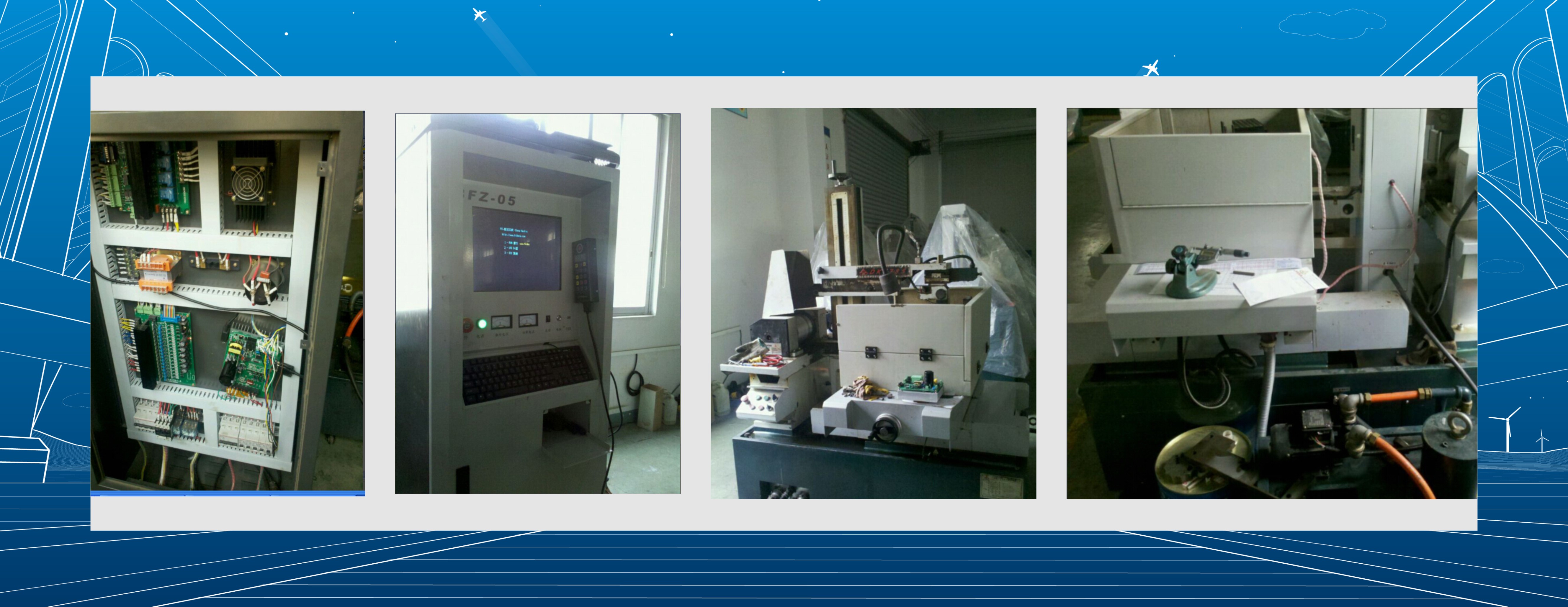
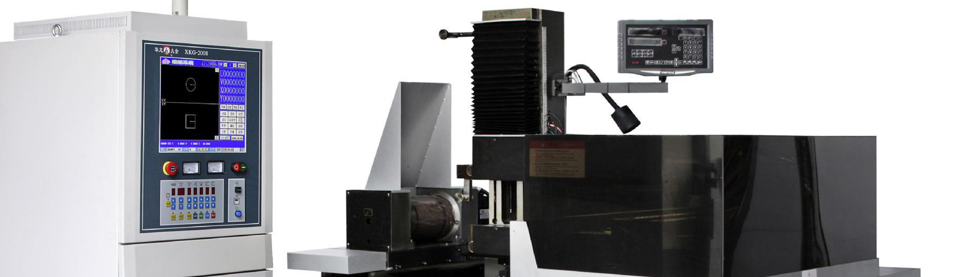
IV. Onsite pictures