This commissioning manual applies to the inverter software version number: (P7.09=9900, P7.10=1.00)
I Quick guide
One-key setting of macro parameters, the inverter enters the default constant pressure water supply mode.
One key to set parameters:P0.01=10
The first row of operation can switch the output frequency, current, and set pressure;
The second row shows the feedback pressure
Default mode scene mode:
The set pressure is 0.500MPa, which can be directly adjusted with the up and down keys on the panel;
Pressure gauge range: 1.0MPa;
Sleep frequency: 25.00HZ
Reach the set pressure value 100%, (P6.37 sleep pressure percentage)
Sleep after 5 seconds; (sleep determination time P6.38)
The panel displays the sleep state of SLEEP.
80% lower than the set value, (P6.35 wake-up pressure percentage),
Restart after 2 seconds. (Wake up determination time P6.36)
II Related parameter description
|
function code |
Item |
Description |
|
P0.01 |
P0.01=10 Constant pressure water supply mode |
Set P0.01=10 to set the default parameters with one key. If you need to adjust other more parameter functions, please refer to the description of water supply parameters. |
|
P6.02 |
Feedback pressure signal:0:VI Remote pressure gauge(0-10V) 9:CI Pressure Sensor(4-20mA) |
Feedback signal settings are generally divided into: Remote pressure gauge (voltage type) Pressure sensor (current type) |
|
P6.04 |
Pressure gauge/sensor Range |
Pressure gauge/sensor Range |
|
P6.06 |
Proportional gain |
This parameter can adjust the speed of system adjustment response |
|
P6.30 |
Given pressure |
Set the target pressure, which can be adjusted by the up and down keys on the panel |
|
P6.31 |
Set the maximum pressure value with the up and down keys |
Set the maximum pressure limit value with the panel up and down keys |
|
P6.32 |
Set the minimum pressure value with the up and down keys |
Set the minimum pressure value with the panel up and down keys |
|
P6.33 |
Alarm upper limit pressure output |
Multifunction switch output (relay output) function 42 |
|
P6.34 |
Alarm lower limit pressure output |
Multi-function switch output (relay output) function 43 |
|
P6.35 |
Awakening pressure level |
In the sleep state, the inverter enters the running state if it is lower than this level and after the judgment time of P6.36 |
|
P6.36 |
Wake up pressure preparation continuous time |
- |
|
P6.37 |
Sleep pressure level |
In the running state, after reaching the sleep condition, it enters the sleep state after the judgment time of P6.38. The panel of the inverter in the sleep state displays SLEEP. |
|
P6.38 |
Sleep pressure level continuous time |
- |
|
P6.39 |
Sleep frequency |
The lower limit frequency of the inverter operation and the judgment of the sleep condition according to the setting of P6.41 |
|
P6.40 |
Sleep frequency continuous time |
- |
|
P6.41 |
Units place: Sleep selection 0:Sleep frequency conditions are valid 1:Invalid sleep frequency condition Tens place: percentage 0:Awakening sleep pressure is the actual pressure 1:Wake up sleep pressure as a percentage of the set pressure |
Sleep selection: When the sleep frequency is invalid, when the sleep pressure level is reached, the condition is satisfied. When the high-level water supply or the slender pipe cannot enter the sleep state, the sleep frequency must be selected to be valid. Percentage: This bit selects whether the wake-up sleep pressure is the actual pressure or the set pressure percentage. |
|
P6.42 |
Locked-rotor judgment time |
Factory value 60 seconds |
III Wiring diagram
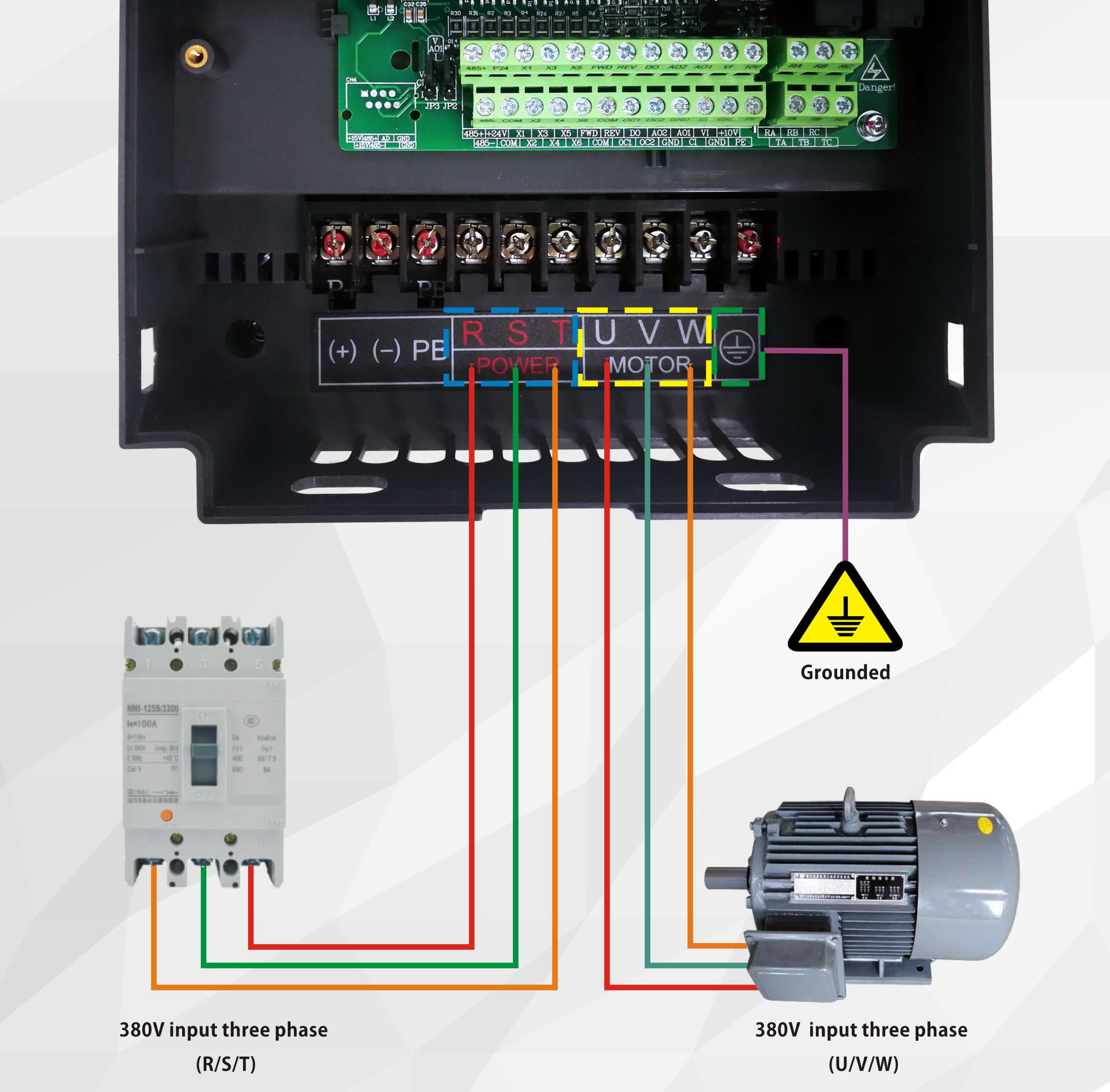
3.1 Main circuit wiring diagram
The following figure takes 7.5KW as an example. Among them, the three-phase power input is R/S/T, and the three-phase output U/V/W is connected to the motor. For details, please refer to the user manual.

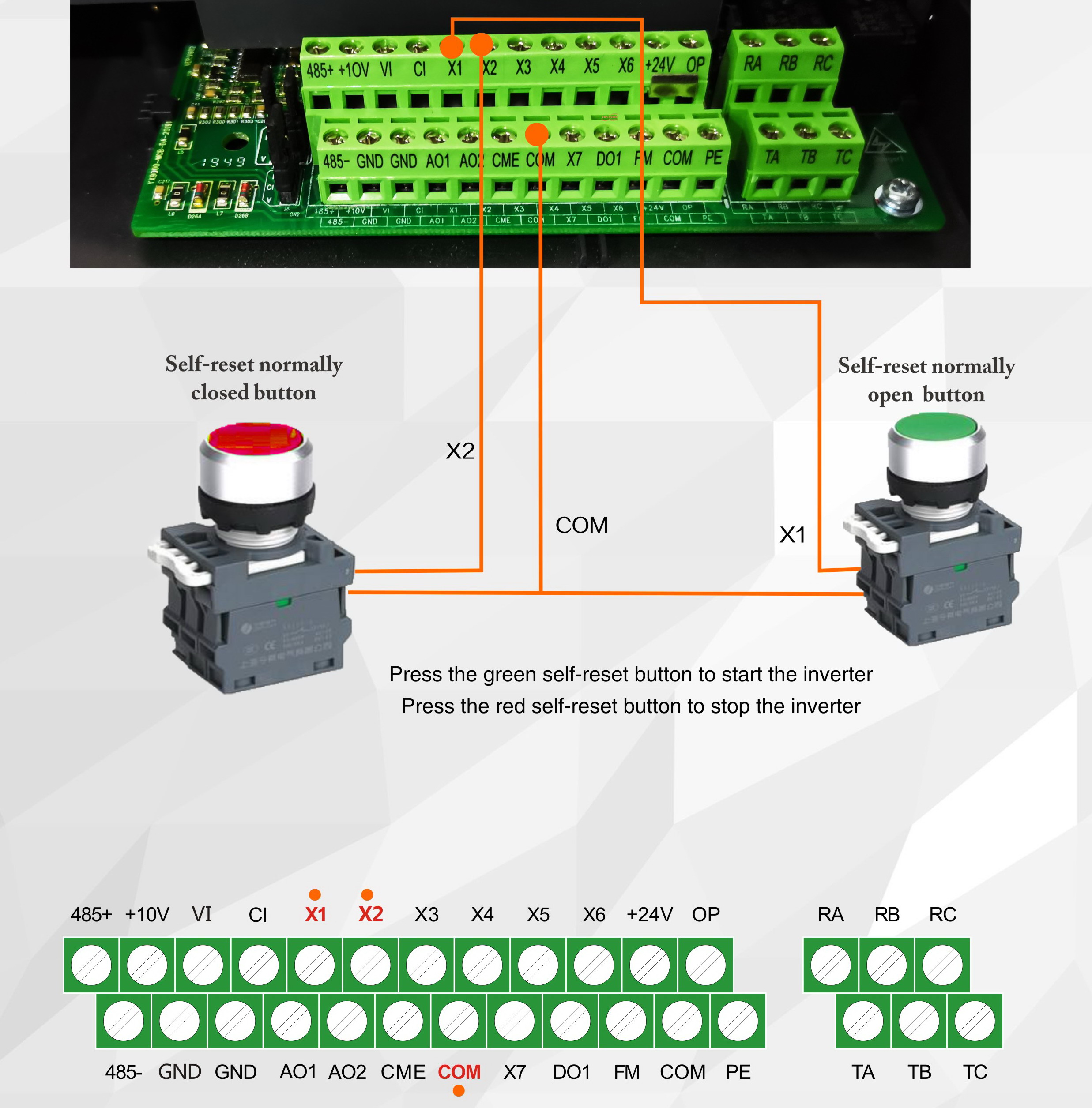
3.2 Schematic diagram of external start and stop(Two-wire system (parameter:P0.03=1)


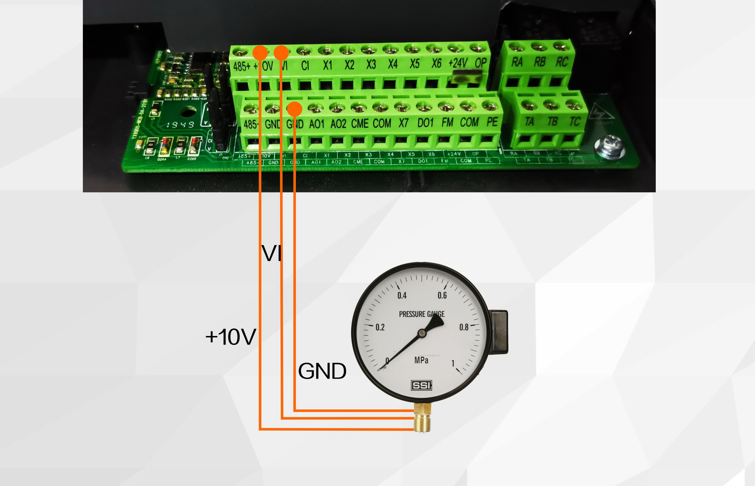
3.3 Wiring diagram of pressure gauge (parameter: P6.02=0)

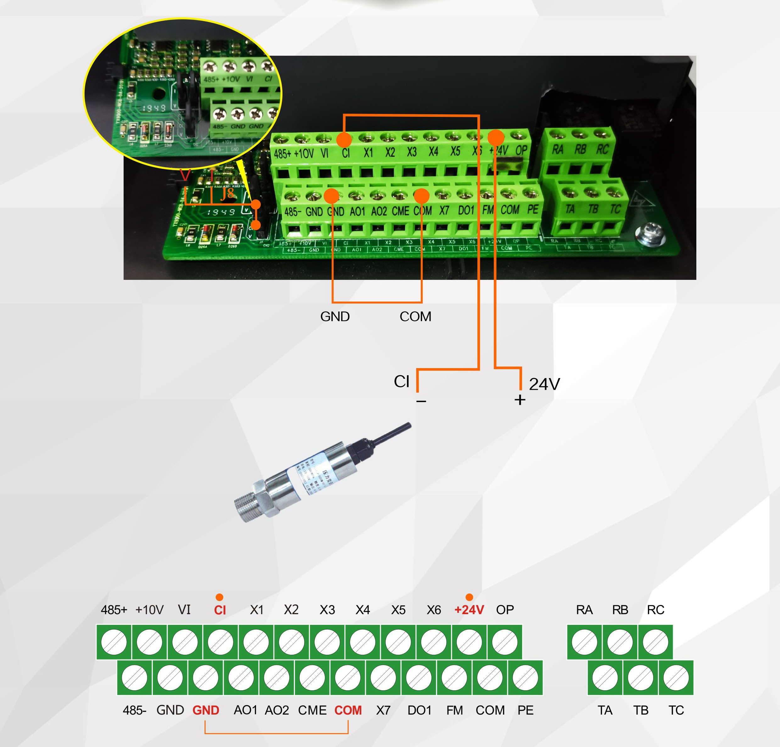
3.4 Pressure sensor two-wire wiring diagram (P6.02=9, CIN jumper to I side)


 Back to list


